
DISTRIBUTION TRAINER
Demonstrates how electricity is distributed and protected. Investigates distribution through transformers, radial and ring-main circuits, efficiency and regulation.
OR CALL US TO DISCUSS+44 1159 722 611
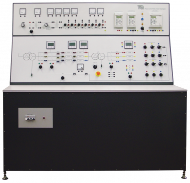
The Distribution Trainer examines different parts of electrical power distribution, from basic circuits to balanced and unbalanced three-phase systems.
The console has two working sections:
- An upper panel that shows the basics of distribution, and
- A lower panel that shows more advanced three-phase power distribution.
The upper panel includes low-voltage a.c and d.c supplies, a set of lamps and variable resistances. The resistances simulate a feeder cable and the lamps simulate loads. Students may connect the feeder circuit to learn the principles of ring main and radial circuits. The low-voltage a.c supplies may be connected to show the principles of regulation.
The lower panel includes connections to two three-phase transformers, lines and loads to simulate industrial power distribution. One transformer reduces the voltage from the incoming supply to the correct value for the experiments. This is the ‘line power’ transformer. The other transformer reduces the line voltage down to 110 V and acts as the ‘line receive’ transformer. Its primary tappings are adjustable and its secondary winding star point can be connected to earth.
The panels include all current, voltage and power meters needed for the experiments.
For protection tests, the circuits include current transformers to connect to the protection relays fitted to the control panels.
The user connects and sets the protection relays to detect line and earth currents. The relays also monitor and measure fault events and disturbances for fault analysis. The user sets the two most simple relays from their local control panels. The more complex relay is set from its local panel, or by a cable link to a suitable computer and software (included). When the user applies a circuit fault, the relays open circuit-breakers in the test circuits. The circuit-breakers also include hand-operated switches, and lamps. The lamps show whether the circuit-breakers are open or closed.
Supplied with the equipment is a set of shrouded leads for the user to connect the test circuits together.
The unit includes an emergency switch, a mains supply isolator and protection fuses.
Supplied with a comprehensive user guide which includes equipment descriptions, theory and experiments. Also, the open and flexible structure of the equipment makes it ideal for student projects and for lecturers to create their own experiments.
- AC/DC transmission
- Radial and ring systems with different load types
- Distribution losses and efficiency
- Voltage control through reactive power compensation
- Use of a tapped distribution transformer for load voltage control
- Three-phase distribution system with balanced and unbalanced loads
- Effect of an open-circuited neutral conductor on voltage across a single-phase load
- Effect on line current of improved power factor
- Distribution system under faults
- Relay discrimination